Fuel oil burner
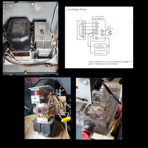
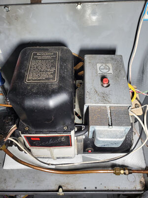
The fuel oil burner for my home furnace system.
Replacement control system
Honey Protectorelay® Oil Burner Control
- Mfg. #: R8184M1051
- R8184M includes 40 VA transformer and Y and G terminals for connection of cooling equipment
- Mounts on standard 4 x 4 in. junction box
- C554A Cadmium Sulfide Flame Detector and a 24 Vac thermostat required
History
Old primary controller
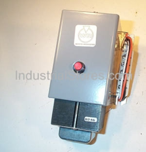
White-Rodgers 668-451 Kwik-Sensor Cad Cell Relay Oil Burner Control 2-Wire 45-Second Timer & External Transformer
This is a "stack relay" device — an older technology.
Specifications
ELECTRICAL DATA
Input voltage: 120 VAC, 60Hz.
Maximum Load Current:
Oil Burner Motor (Orange Wire): 10 Amps F.L. 60 Amps L.R.
Ignition Transformer: 360VA (3.0 Amps)
Relay Voltage: 24 Volts AC, 60Hz.
Room Thermostat:
Set adjustable heat anticipator at 0.4 Amps.
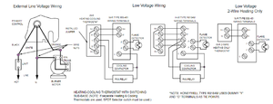
Low Voltage Rating (Terminals R&C):
Maximum cooling load of 40VA @ 24v. 60 Hz.
Continuous duty. W & C cycled through thermostat.
Safety Timing: 45 seconds
- TYPE 668-451 - Emerson Climate Technologies @ Emerson (PDF)
Testing
The following control checks should be made after each installation to insure that the controls are correctly wired and functioning properly.
1. Open the main line switch.
2. Adjust thermostat or operating control to call for heat.
3. Operate the manual reset button on top of control.
4. Make certain that high limit control is set at the correct temperature.
5. Open the hand valve in the oil line. The system is now ready for the following tests.
A. NORMAL CYCLE:
Close the line switch. The burner should start and continue to run normally. (If burner starts, establishing flame, but then locks out on safety, make “Flame Detector Check” at this time.)
B. SAFETY TIMING:
1. Let the burner run for about 5 minutes. Then remove one of Flame Detector leads from the “F” terminals. After a time period corresponding to the safety timing has elapsed, the control should lock out on safety, stopping the burner. 2. Open the line switch. 3. Replace Flame Detector lead removed in step 1. 4. Wait 3 minutes. Then operate the manual reset button on top of control.
C. HIGH LIMIT AND THERMOSTAT CHECK:
1. Close the line switch to start the burner.
2. Lower the setting of the high limit control to its lowest setting. This should stop the burner, unless furnace or boiler temperature is below the minimum setting of the high limit.
3. Return high limit control to its proper setting. Burner should restart.
4. With the burner running, turn thermostat to its lowest setting. This should stop the burner, unless actual room temperature is below the lowest setting of the thermostat. On systems supplying domestic hot water, burner will continue to run if low limit control is not satisfied.
5. Return thermostat to its proper setting.
D. FLAME DETECTOR CHECK: (This test is not required if the control performs as described in test A.)
If the burner starts but the control locks out (stopping the burner), check the flame detector as follows:
1. Open the line switch.
2. Connect one end of a wire jumper to one of the “F” terminals.
3. Start the burner by closing the line switch. As soon as the flame has been established, connect the other end of the wire jumper to the other “F” terminal. The control provides NO SAFETY PROTECTION with this jumper installed. DO NOT leave burner in this condition except for making this check. If the control still locks out with the jumper installed, the control should be replaced. If the control does not lock out, however, check the operation of the 956 flame detector as follows:
NOTE
! WARNING Possible Cause of Trouble
- Open circuit in Cell - Replace Cell (or Cell Assembly) of 956 Flame Detector. Do not disturb position of bracket or socket assembly.
- Flame detector improperly positioned - Locate flame detector according to the burner manufacturer’s specifications.
Documentation
- White-Rodgers 668-451 Installation Manual
- Reset Button Operation on Primary Controls for Oil Fired Heating Equipment
- Cad Cell Relay Switches on Oil Burners
- Tech specs, replacement parts
- Tech specs, replacement parts
Safety
- Oil Burner Puffbacks - an explosion of un-burned oil in the combustion chamber of an oil-fired boiler, furnace, or water heater.
See also
- Oil burner @ Wikipedia
- Post @ Facebook


